pvd wick drains
For more detailed specifications, please visit our Data Sheet Library.
Product Information
Engineered specialty wick drain product assists and accelerates the consolidation of saturated, compressible soils
AWD PVD wick drains have set the World standard for over 35 years
Roll Width: 4” (100mm)
Roll Length: 1,000’ (305m)
Custom products available upon request.
What is a Wick Drain?
PVD’s are often referred to as wick drains primarily for two reasons. First, after insertion, the PVD it is cut off with approximately 2’ to 3’ (~1m) sticking out of the ground. Looking across the completed installation area these PVD “tails” resemble a field of candle wicks. Secondly, there is a popular misconception that water is “wicked” up the PVD during consolidation. The reality is that downward pressure of the preload and surcharge mobilizes the pore water to seek out the path of least resistance which happens to be the installed PVD’s.
PVD Product Specifics
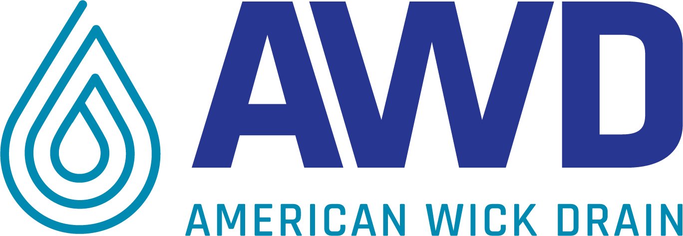
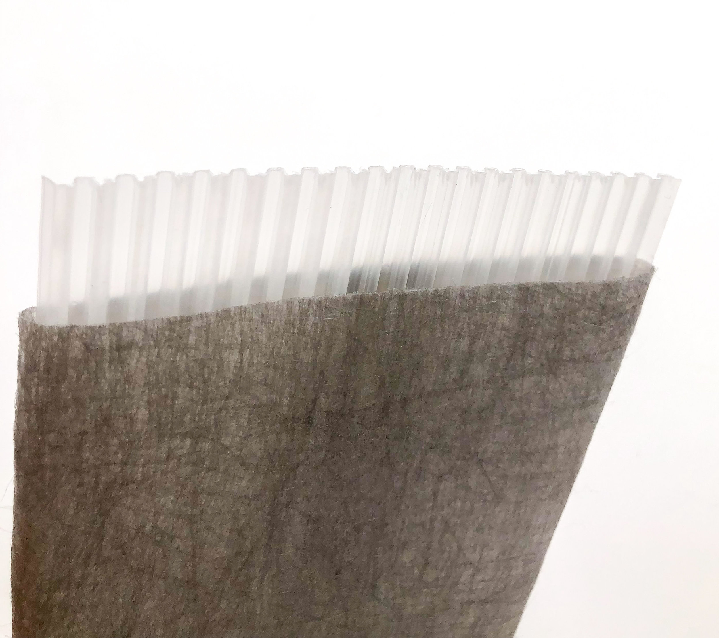
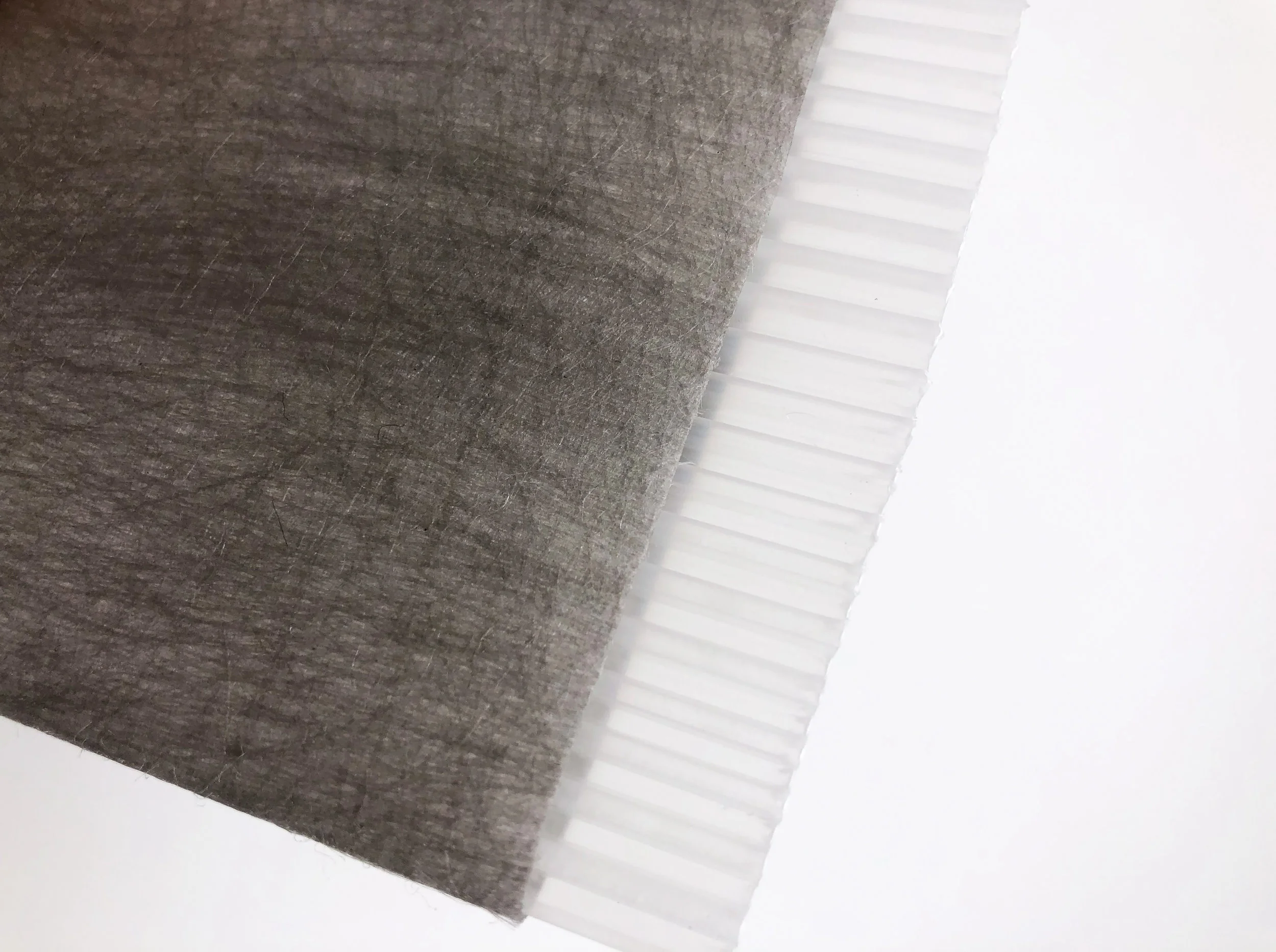
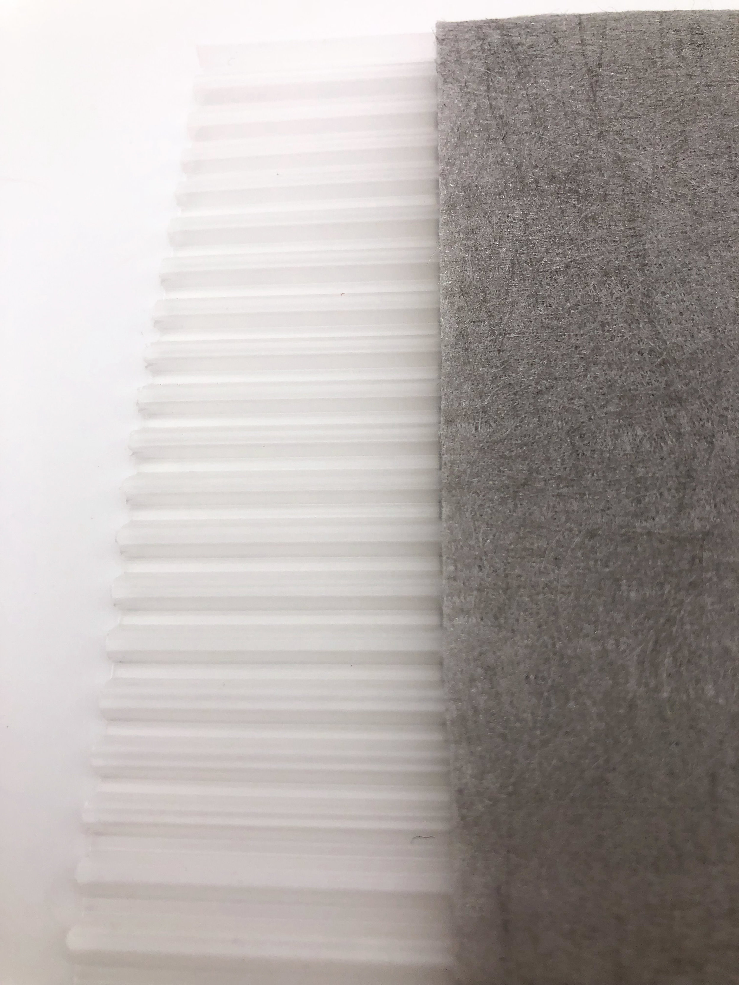
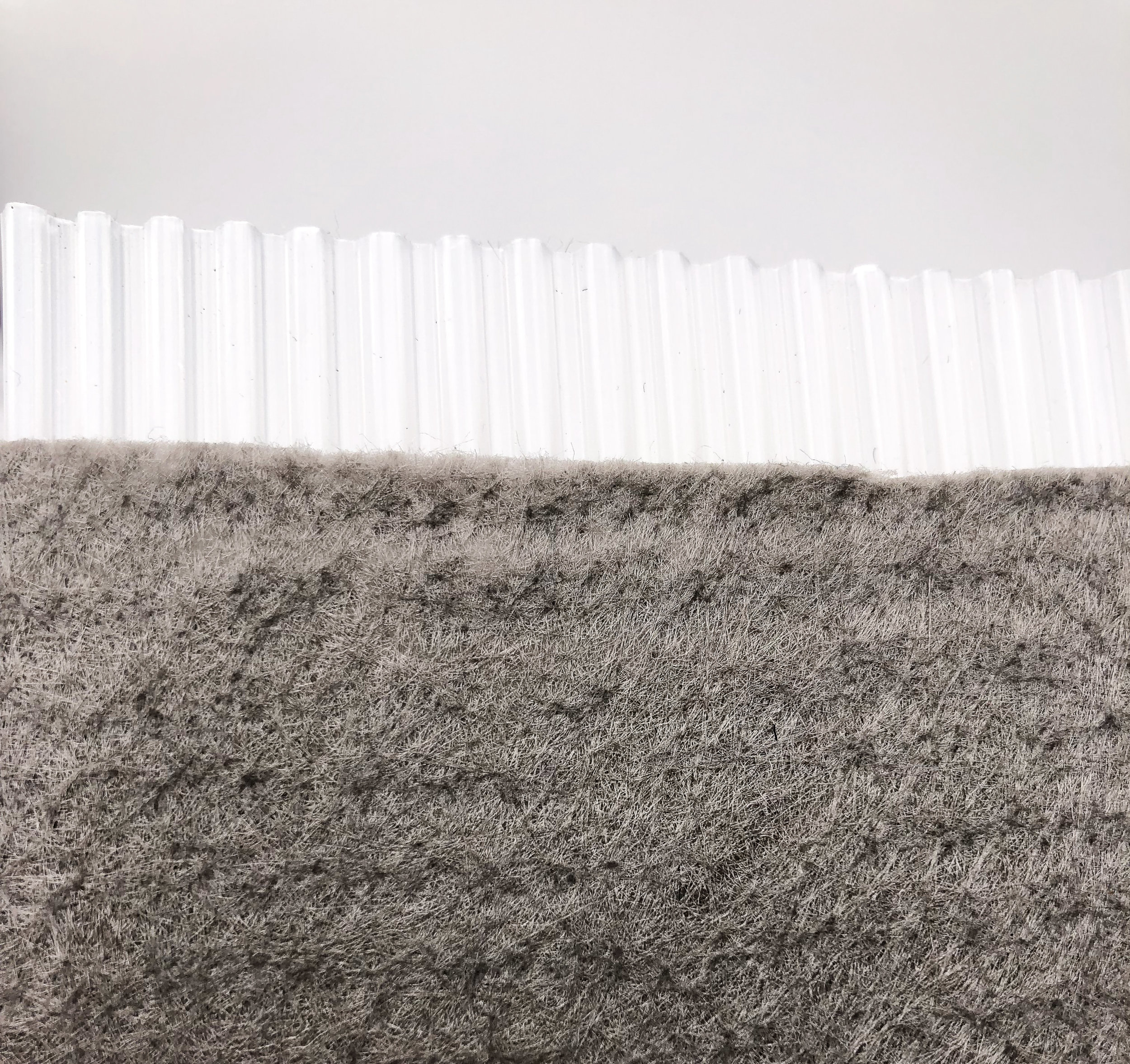
A typical wick drain, or PVD as we will refer to them, is 4” wide and 3/16” to ¼” thick in a rolled format. The cores are typically made of a polymer product with a series of protrusions to create open drainage channels. The core is then wrapped or sealed in a geotextile to prevent soils from entering and potentially clogging the drainage channels formed by the core.
AWD AMERDRAIN™ PVD products consist of an extruded corrugated or finned polypropylene core wrapped in a polypropylene geotextile. The geotextile wrap properties can be general or exclusive to meet the project specifications and are typically a needle punched non-woven or spun bond product. AMERDRAIN™ products typically ship in 1,000’ (330m) rolls to the jobsite. Under certain conditions, roll sizes can be customized to maximize packaging on containers for International shipments or to address unique, challenging site conditions.
There are more vertical drain system approaches with similar general principals and performance. The cost advantage that PVD’s present have provided a distinct advantage over other vertical drain systems making the use of PVD’s primarily exclusive to a vertical drain approach to ground modification.
Primary PVD Benefits
The primary use of a PVD is for the consolidation of soft soils in conjunction with a preload and/or surcharge.
The benefits a PVD vertical drain system approach offer is:
Decreased consolidation or settlement time with minimal to no post-construction settlement. This can contribute to an accelerated project schedule.
Decreased volume of preload and/or surcharge material required to mobilize settlement. This contributes to a lower project cost
Increased bearing capacity of the soil through consolidation to provide long term support and stability for the constructed elements of the project.
Soil Information and Feasibility
Most commonly PVD’s are used to modify soils that are highly compressible, mostly to fully saturated and possess low permeability in their natural state. Some of these soils are typically identified as silts, clays, organic silts and clays, muck, peat, swamps, and sludge.
Ordinarily, PVD’s are not used in materials with a high organic content. These materials usually exhibit significant post-construction secondary settlement and are not suitable for long term load support and stability. In general, for PVD’s to be effective, the soils should be saturated and normally to slightly over-consolidated prior to placement of the preload and/or surcharge.
Advantages of PVD’s
There are many advantages to using a PVD soil consolidation approach to ground modification.
Some of these are:
Economical – PVD cost is typically much less than other vertical drain systems.
High Productivity – Production rates for PVD installation far exceed those of other vertical drain systems. Production rates of 20,000’ per day, per rig are usual. Under ideal conditions these installation rates can double or triple.
Continuous Drainage Path – PVD’s provide a continuous, uninterrupted drainage path even through consolidation or displacement.
Minimal In Situ Soil Displacement – The mandrel used for PVD insertion creates minimal disturbance and displacement during installation.
Better Quality Control – A factory manufactured PVD ensures a high level of field performance and allows installers and inspectors to concentrate on drain placement and final tip elevation.
Better Equipment – The equipment used to install PVD’s continues to evolve and achieve higher levels of performance under varying conditions. Rigs are available to provide a safe and reliable installation under practically any project conditions.
Environmentally Friendly – The high production rates result in less days on the project. The minimal disturbance means less spoils and soil waste to manage. The compact, rolled format takes less are to store material and little to no waste following installation.
Potential Disadvantages
There are very few disadvantages to using PVD’s for improved soil consolidation.
We would be remiss to not acknowledge that there are a couple of concerns to consider:
PVD Rig Limitations – PVD rigs are typically several feet taller than the longest installed PVD length. Projects requiring a 90’ deep PVD may require a PVD rig with a mast of 95’ to 100’ tall. This could be problematic where overhead obstructions such as power lines or structures exist.
PVD Material Storage – While PVD product storage requires minimal space, they are required to be protected from extended direct sunlight if storage time will exceed 30 days. Contact AWD for some of the ways we can help manage this concern with UVI wraps to extend and mitigate outdoor storage concerns.
PVD Installation
The typical method used to install PVD’s consists of an installation mast which contains the steel mandrel, PVD reels and the mechanism to provide the static and/or vibratory insertion force. The mast is attached to a track excavator or crane depending on the installation depth or height of the installation mast.
See Figure 1 for further information.

Figure 1
The typical mandrel used in the USA is either diamond or rectangular shaped, hollow steel tube with a size of approximately 5” by 2”. The PVD is fed through the interior of the mandrel from PVD rolls mounted on the mast reel near the base of the mast. The ground operator feeds the PVD up the inside of the mast, over a sheave at the top of the mast and down through the steel mandrel where it exits at the bottom near the ground.
The PVD is threaded through an anchor at the bottom of the mandrel and inserted back into the bottom of the mandrel. This anchor is usually an 8” piece of number 4 or 5 rebar or a sheet metal anchor plate. The anchor plates are made from thin steel designed to deform upon installation and fold up around the edges of the steel mandrel. A small handle or bail is spot welded to the anchor plate to wrap the PVD through prior to reinsertion into the bottom of the mandrel.
See Figure 2 and 3 for additional information.
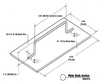
Figure 2

Figure 3
After the PVD has been threaded around the anchor and the anchor is in place, the mast is positioned over the insertion point and the mandrel is inserted into the soil. The PVD remains protected by the mandrel during insertion and once the mandrel tip reaches the desired elevation the mandrel is retracted, leaving the anchor and PVD in place. Once the mandrel is fully retracted, the ground operator pulls additional PVD from the bottom of the mandrel, cuts the PVD leaving a 2’ to 3’ (~1m) tail above the ground and attaches another anchor for the next PVD insertion.
When the PVD roll on the mast reel ends, the ground operator pulls PVD from the next roll on the reel and slices this roll to the previous roll end for uninterrupted drain continuity. To splice a PVD the geotextile wrap is slit and folded back from one end exposing 6” to 12” of PVD core. This bare PVD core is inserted into the other wrapped PVD end, the slit geotextile wrap is folded back into place, and the overlapped splice area is connected by using 6 to 10 staggered staples on both edges and in the middle of the spliced PVD section.
See AWD Technical Detail 280 for additional information and details on proper PVD splicing.
Installation continues until all PVD’s have been inserted at the designed locations to the designed depths.
When this step is complete it is time for installation of the drainage layer.
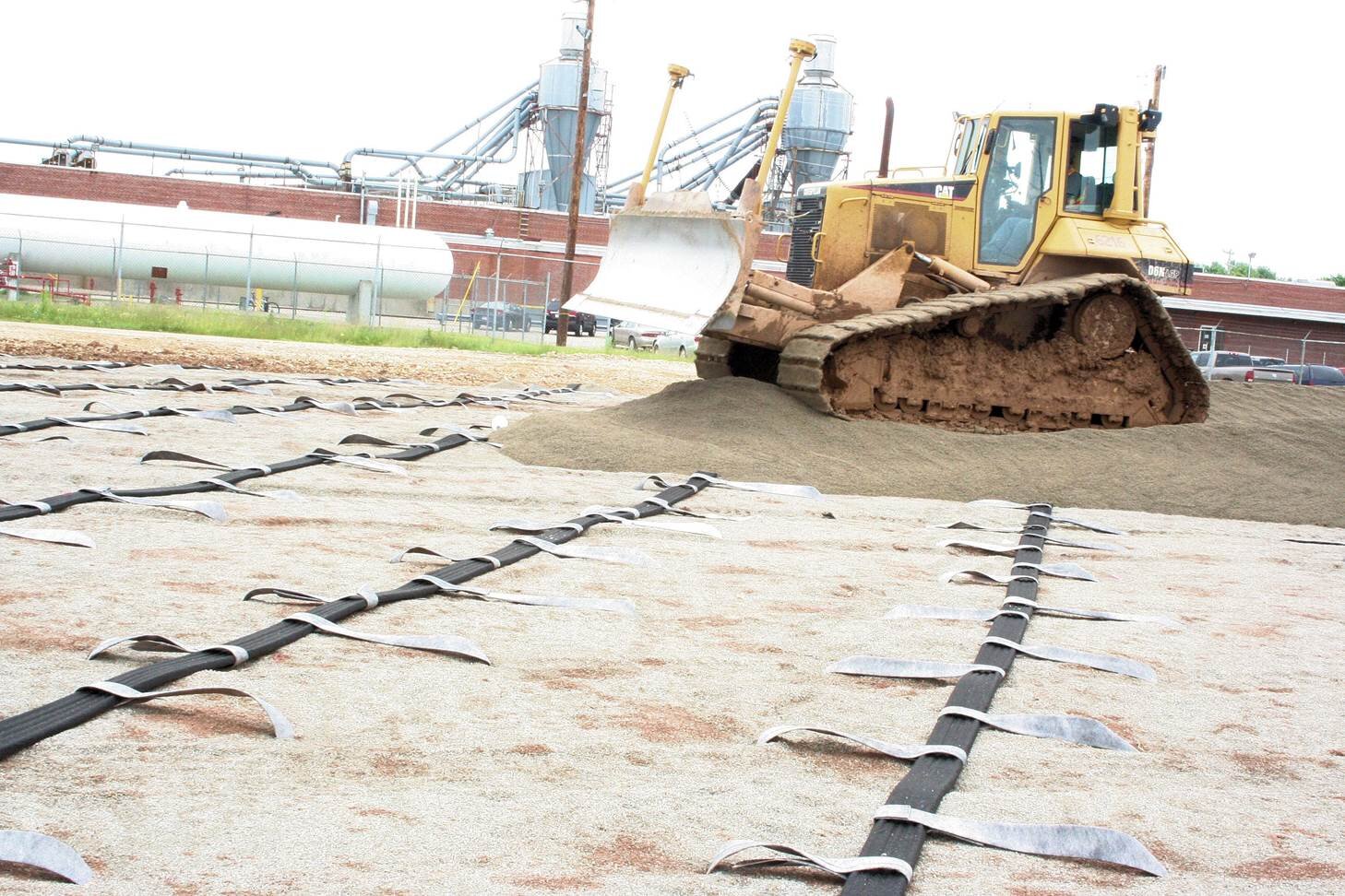
PVD Drainage Layer
The drainage layer is a critical piece to the completed vertical drain system. The drainage layer provides a method of conveyance to a discharge point for water from the vertical drains. Historically this has been accomplished by installing a layer of granular material, typically open graded stone, over the entire consolidation area. Due to the cost of the granular material and additional cost to import and spread, many projects now employ AWD SITEDRAIN Strip Drain products to reduce or eliminate the additional granular material and dramatically increase the efficiency of the drainage layer. For additional information request AWD Technical Bulletin “Horizontal Drainage Layer Applications: Drainage Aggregate with and without 6-in Geocomposite Strip Drain”.
Attaching AWD PVD Drains to AWD SITEDRAIN Strip Drain can be accomplished with either the “Belt” method or the “Nail” method. AWD can provide Technical Bulletins for each method to help determine which is best for your project and site conditions.